Optical Transceiver Signal Conversion: Electrical-to-Optical and Optical-to-Electrical Explained
A focused guide to E/O and O/E conversion, modulation, photodetection, DSP, FEC and signal integrity inside optical transceivers.
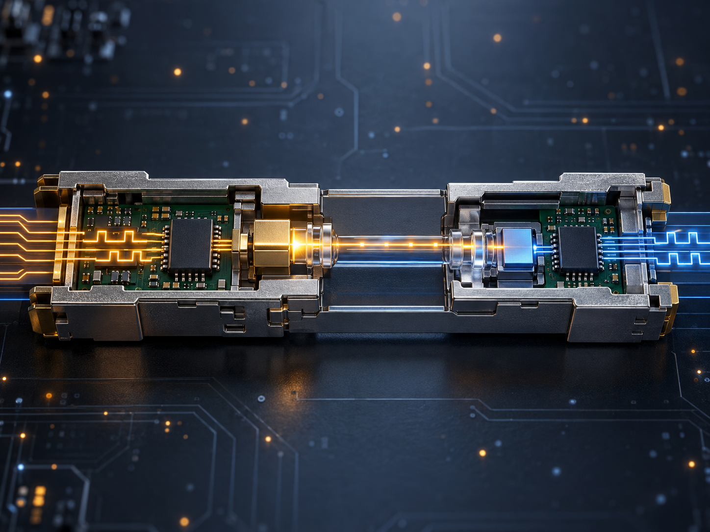
What signal conversion actually means
Signal conversion is more complex than turning a light on for one and off for zero. A host sends high-speed differential waveforms through SerDes lanes. Under limited bandwidth, noise and jitter, the module may recover or reshape the data before a laser or external modulator places information onto an optical carrier. At the receiver, a photodiode converts incident light into a small current, and a transimpedance amplifier plus following electronics recover a host-compatible electrical waveform. Protocol data generally remains unchanged, but lane count, symbol rate, coding and FEC boundaries can be remapped. Package, electrical interface and optical PMD describe different layers, so two products that both perform E/O and O/E conversion are not automatically interoperable.
Electrical-to-optical conversion
The transmit path commonly begins with input equalization, clock-and-data recovery or DSP. A retimed module restores timing and reduces jitter; an LPO module removes much of the module DSP and depends more heavily on host signal quality. Drivers supply the voltage and current required by a VCSEL, DML, EML or silicon-photonic modulator. NRZ uses two amplitude levels and carries one bit per symbol. PAM4 uses four levels and carries two bits per symbol, increasing bit rate at the same symbol rate but shrinking eye openings and increasing sensitivity to linearity, noise and reflections. Optical lanes can enter a parallel connector or be combined onto duplex fiber by CWDM or LAN-WDM multiplexing. Automatic power control and temperature compensation help maintain laser output as supply and environment change.
System design must preserve margin across the complete path. Typical values are useful for comparison, but acceptance should use guaranteed limits and worst-case combinations. Engineers need to account for host-board loss, connectors, fiber attenuation, temperature, aging and neighboring-port heat. They should document where retiming, gearbox functions and FEC reside, because moving a function between host and module changes power, latency, diagnostics and interoperability.
Capacity should be modeled at several time horizons. The first-year design may optimize cost, while the three- or five-year design must preserve pathways, ports, fibers and thermal headroom for higher speeds. Breakout can change one high-rate interface into several services, but it also changes fiber counts, patching and failure impact. Teams should compare an incremental upgrade with a planned migration that replaces optics, switches and selected trunks together. The correct choice depends on traffic growth, maintenance windows and how much installed cabling can be reused without compromising loss or polarity.
Physical implementation deserves the same discipline as electronic design. Bend-radius violations, dirty end faces, overfilled trays and poorly supported jumpers can consume margin or create intermittent failures that are difficult to reproduce. Installation records should include cable type, route, length, connector count, measured loss and the test instrument settings. Changes should update both labeling and the logical inventory. This evidence shortens fault isolation and prevents a future team from assuming that a documented route still matches the fibers in the rack.
Power, cooling and service access must be reviewed together. Dense ports may reduce rack space while increasing local heat and making connector inspection harder. A production layout should preserve airflow, finger access and safe replacement space at the same time.
Operations teams should retain a baseline for every production link: module identity and firmware, transmit and receive power, temperature, voltage, error counters and FEC statistics. Trend data helps separate gradual contamination or component aging from abrupt fiber damage. Qualification should include cold start, repeated restart, hot insertion, firmware change, full port population and sustained traffic. A standards-compliant interface is an essential starting point, but repeatable system testing establishes usable margin.
Optical-to-electrical conversion
On receive, a WDM module first separates wavelengths, while a parallel module routes each fiber directly to its corresponding lane. A PIN or avalanche photodiode produces current related to incident light, and a transimpedance amplifier converts and amplifies that small current into voltage. Limiting amplifiers suit decision-based receivers; linear amplifiers and ADCs preserve more amplitude information for DSP. Equalizers compensate for bandwidth roll-off and some channel distortion, clock recovery determines sampling position, and decision logic reconstructs NRZ or PAM4 symbols. A coherent receiver uses a local oscillator, optical hybrids and balanced photodetectors to capture amplitude, phase and polarization. DSP then compensates chromatic dispersion, polarization rotation and frequency offset, enabling higher spectral efficiency over longer distances.
FEC, monitoring and verification
High-speed conversion is affected by laser noise, receiver thermal noise, dispersion, reflections, crosstalk, connector loss and manufacturing tolerance. FEC allows operation at a defined pre-FEC error rate and corrects errors with redundant check information, but post-FEC performance can deteriorate sharply once the threshold is exceeded. Testing must therefore go beyond a link-up indication. It should examine the transmit waveform or TDECQ, receiver sensitivity, stressed input, BER, FEC margin, optical power, temperature and long traffic runs. Digital diagnostics report temperature, voltage, bias and optical power, but their accuracy and thresholds need interpretation. Sources include the Ethernet Alliance PCS/PMA explanation, its FEC testing guidance, and a 100G ER4 functional example.