Optical Transceiver Compatibility and Specifications: A Practical Verification Guide
How to verify host, electrical, optical, management, fiber and software compatibility before installing a transceiver.
Compatibility has several layers
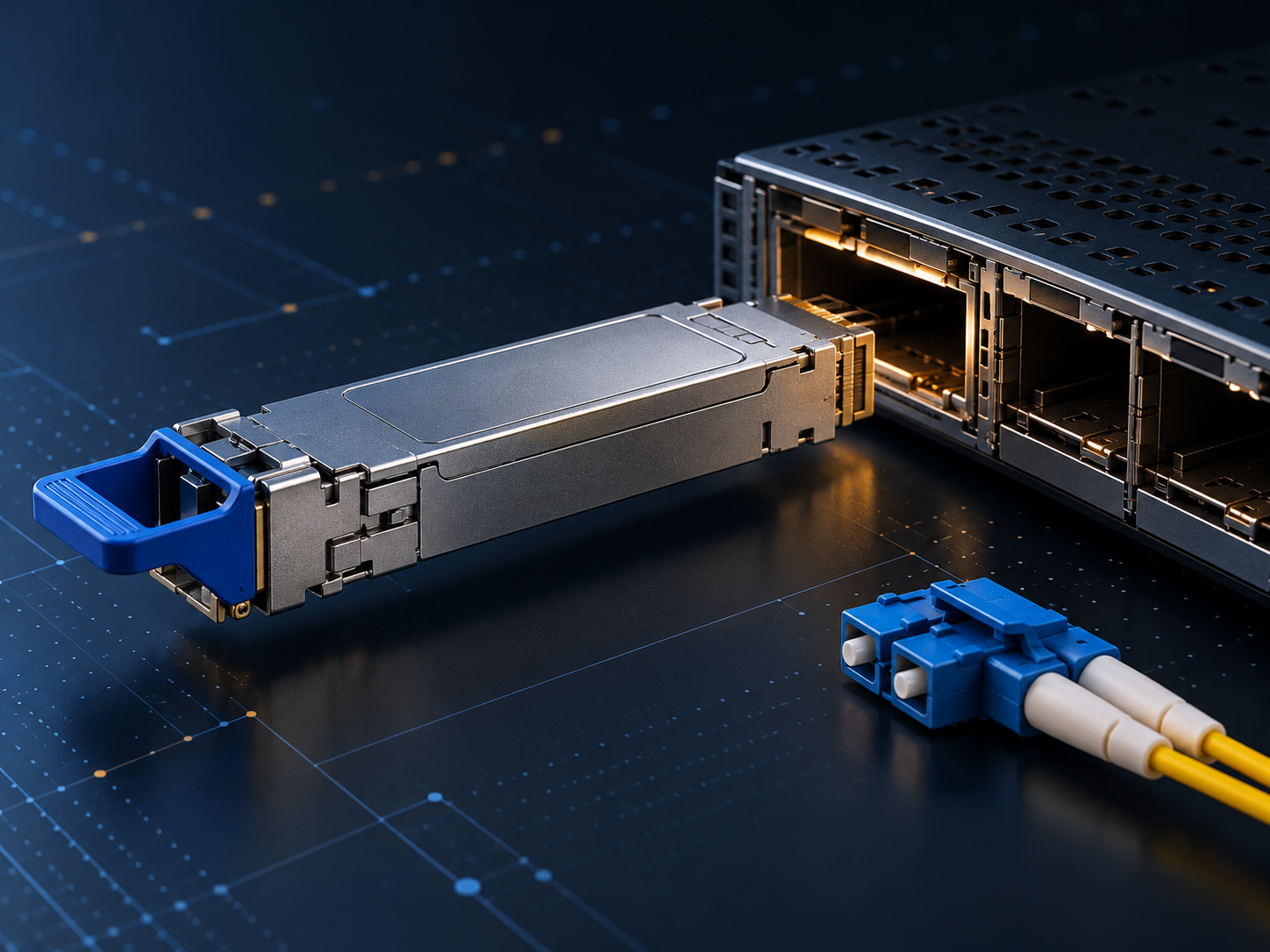
A module that fits only proves that the mechanical shape may match; it does not establish that the host will recognize it or that a link will operate. Complete compatibility has at least six layers: module and cage, host electrical interface, protocol and rate, optical PMD, management interface, and software policy. The QSFP28 shape, for example, can carry 100GBASE-SR4, CWDM4, LR4, PSM4, an AOC or a DAC, each with different fiber, wavelengths, connectors and lane structures. Even identical LC receptacles do not guarantee interoperability. A duplex 1310 nm LR optic cannot link to an unrelated single-fiber BiDi optic. Vendor compatibility matrices may also restrict support to specific platforms, line cards and minimum software releases.
Read the specification correctly
First confirm aggregate rate and the host signal per lane. A common 100G QSFP28 interface uses 4×25G NRZ, while 400G QSFP-DD may use 8×50G or 4×100G PAM4. Verify support for the intended Ethernet, Fibre Channel or transport protocol and determine whether FEC is implemented by the host or module. Optical review should cover transmit wavelength, receive range, minimum and maximum power, sensitivity, overload, extinction ratio, dispersion tolerance and maximum channel loss. Distance is an outcome of the specified channel, not an independent promise; connectors, splices, splitters, bends and aging consume margin. The media must match—SMF, OM3, OM4 or OM5—as must LC or MPO polarity and APC or UPC end-face type.
Practical qualification must treat the module, host and fiber plant as one system. Engineers should record lane configuration, modulation, FEC responsibility, connector loss, operating temperature and firmware before comparing alternatives. Testing should include cold start, repeated insertion, sustained traffic, diagnostic accuracy and fully populated thermal conditions. A specification identifies a permitted interface; it does not guarantee equal margin, software behavior or field support across every vendor combination.
A link budget should use worst-case transmit power and receiver sensitivity rather than typical values. Connector loss, splices, patch panels, wavelength-dependent loss, aging and a deliberate engineering reserve all belong in the calculation. Receive overload matters as well: an optic designed for a long span can receive too much power on a short patch unless attenuation is added. For parallel links, every lane must pass, and polarity must map each transmitter to the correct receiver. For wavelength-multiplexed links, both ends must use the same wavelength grid and lane order.
Operations planning is equally important. The monitoring system should collect temperature, voltage, transmit and receive power, alarms and pre-FEC error indicators where available. Baselines recorded after installation make gradual contamination, laser aging or rising temperature easier to distinguish from an abrupt fiber break. Cleaning procedures, inspection tools, spare placement and rollback instructions should be documented before production traffic depends on the link. A module that performs well in a bench test can still create long outages if field staff cannot identify the failing domain or replace it safely.
Power and cooling should be checked at the system boundary. Module wattage is only one part of consumption; host SerDes, retimers, fans and power conversion also contribute. Dense ports can be efficient per transported bit while creating local hot spots, so validation should use adjacent ports, realistic airflow and the highest supported inlet temperature.
Procurement should distinguish a standards-compliant sample from a host-qualified production part. Useful evidence includes a dated compatibility matrix, compliance report, reliability data, manufacturing change-control process and clear warranty ownership. Second sourcing only reduces risk when alternate modules pass the same electrical, optical, thermal and management tests. These checks prevent a familiar connector or matching headline rate from being mistaken for complete interoperability.
Management, coding and diagnostics
Modules report identity, capabilities, temperature, voltage, transmit and receive power, and alarms through management specifications such as SFF-8472, SFF-8636 or CMIS. SNIA explains that CMIS supplies a common management communication and interaction protocol while allowing a module to advertise optional capabilities. This supports shared host software, but does not mean every optional feature is present. Some equipment checks vendor coding, serial information or licensing policy; a third-party module can meet electrical and optical requirements yet still produce a warning or be disabled. Digital diagnostics are useful for trending and fault isolation, but their accuracy and thresholds should be checked and they do not replace a calibrated power meter or bit-error test. Recognition, application selection and breakout should be retested after firmware changes.
A repeatable acceptance checklist
Use a repeatable worksheet. Record device, port, software release, module part number and firmware; check form factor, power class, temperature range, electrical interface, protocol, FEC, wavelength, fiber and connector; calculate the worst-case optical budget and preserve engineering margin. Laboratory acceptance should include cold start, hot insertion, restart, fully populated high-temperature operation, long traffic runs and alarm reporting. When the two ends come from different vendors, retain the exact combination and results rather than recording only that each item is standards compliant. Useful references include the SNIA QSFP compatibility diagrams, SFF-8665 and CMIS discussion, and the Cisco device compatibility matrix.