How Optical Transceivers Work: From Electrical Bits to Light and Back
A clear explanation of the transmitter, receiver, optics, DSP, FEC and management functions inside modern optical transceivers.
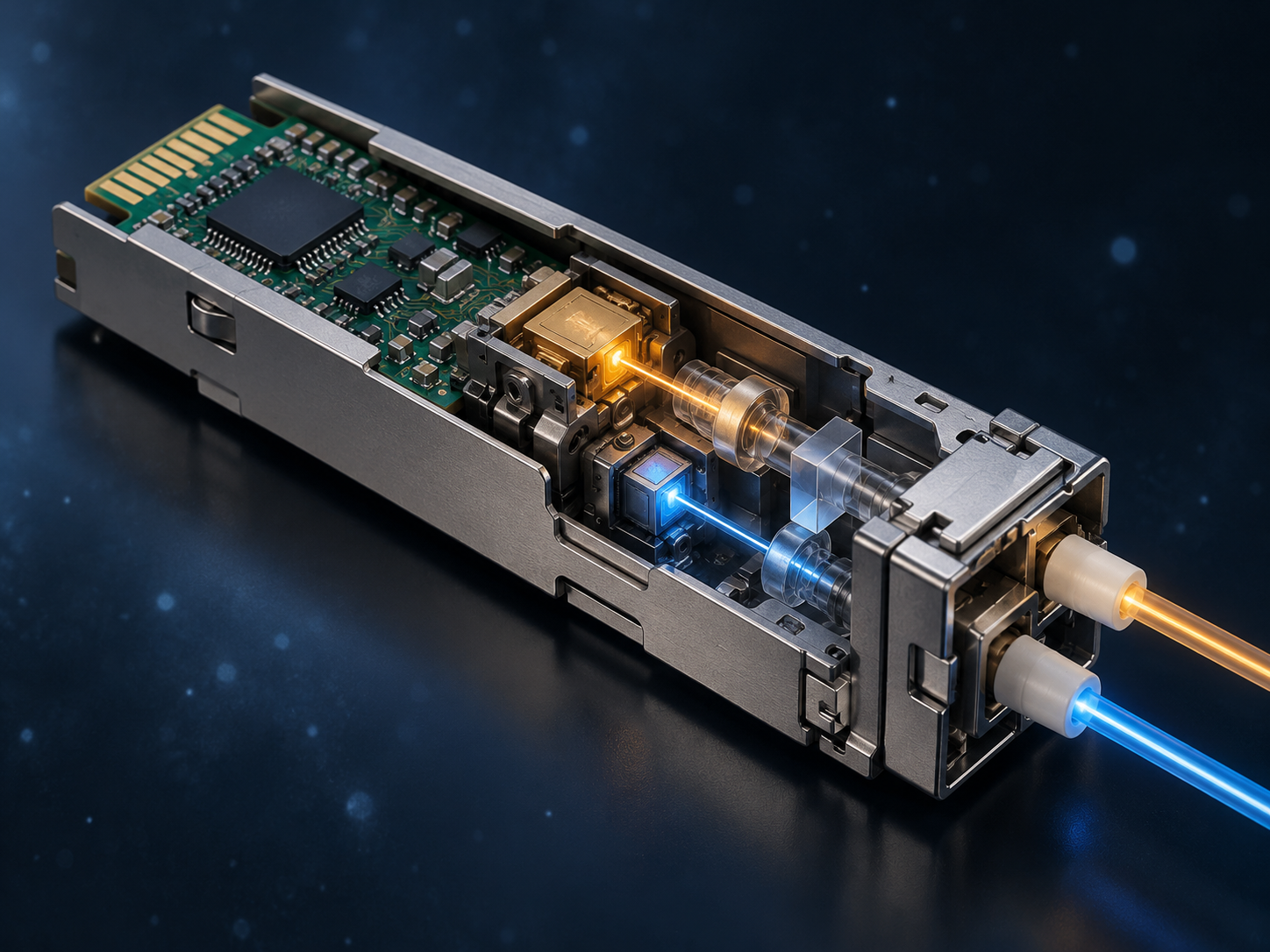
A bidirectional conversion system
An optical transceiver sits between a switch ASIC or network adapter and the fiber. Its central job is to convert a high-speed host electrical signal into light and recover a weak optical signal as electrical data in the opposite direction. Most duplex modules contain separate transmit and receive paths and therefore operate full duplex. The host supplies data, control and power through the card-edge connector, while LC, MPO or another optical interface joins the module to fiber. A form-factor name defines mechanical and electrical boundaries; the actual link capability is also determined by the Ethernet PMD, wavelength, modulation, fiber and FEC. Modern modules monitor temperature, voltage, laser bias, optical power and alarms so the host can assess link health.
The transmit path
On transmit, the host SerDes provides one or more high-speed electrical lanes. Clock recovery, equalization, a gearbox or DSP can retime, map or encode the data, depending on architecture. A driver raises the signal to the level required by the optical source. Short-reach modules often directly modulate VCSELs; single-mode modules may use DFB or EML lasers; silicon-photonic designs often combine a continuous-wave laser with Mach–Zehnder modulators. NRZ represents one bit with two levels, while PAM4 uses four amplitude levels to carry two bits per symbol. PAM4 increases lane rate but is more sensitive to noise, linearity and jitter. Multiple optical lanes can enter separate fibers or be combined onto one fiber by a wavelength multiplexer.
Practical qualification must treat the module, host and fiber plant as one system. Engineers should record lane configuration, modulation, FEC responsibility, connector loss, operating temperature and firmware before comparing alternatives. Testing should include cold start, repeated insertion, sustained traffic, diagnostic accuracy and fully populated thermal conditions. A specification identifies a permitted interface; it does not guarantee equal margin, software behavior or field support across every vendor combination.
A link budget should use worst-case transmit power and receiver sensitivity rather than typical values. Connector loss, splices, patch panels, wavelength-dependent loss, aging and a deliberate engineering reserve all belong in the calculation. Receive overload matters as well: an optic designed for a long span can receive too much power on a short patch unless attenuation is added. For parallel links, every lane must pass, and polarity must map each transmitter to the correct receiver. For wavelength-multiplexed links, both ends must use the same wavelength grid and lane order.
Operations planning is equally important. The monitoring system should collect temperature, voltage, transmit and receive power, alarms and pre-FEC error indicators where available. Baselines recorded after installation make gradual contamination, laser aging or rising temperature easier to distinguish from an abrupt fiber break. Cleaning procedures, inspection tools, spare placement and rollback instructions should be documented before production traffic depends on the link. A module that performs well in a bench test can still create long outages if field staff cannot identify the failing domain or replace it safely.
Power and cooling should be checked at the system boundary. Module wattage is only one part of consumption; host SerDes, retimers, fans and power conversion also contribute. Dense ports can be efficient per transported bit while creating local hot spots, so validation should use adjacent ports, realistic airflow and the highest supported inlet temperature.
Procurement should distinguish a standards-compliant sample from a host-qualified production part. Useful evidence includes a dated compatibility matrix, compliance report, reliability data, manufacturing change-control process and clear warranty ownership. Second sourcing only reduces risk when alternate modules pass the same electrical, optical, thermal and management tests. These checks prevent a familiar connector or matching headline rate from being mistaken for complete interoperability.
The receive path and error control
At the receiver, a demultiplexer separates wavelengths or parallel fibers map directly to lanes. A photodiode converts photons into a very small current, and a transimpedance amplifier turns that current into a usable voltage. A limiting or linear amplifier then supplies the required gain. Receive DSP and equalization compensate for bandwidth limits, noise and some dispersion, recover timing, and decide the transmitted symbols. High-speed links tolerate a defined level of raw errors, and FEC uses redundant check information to correct errors at the receiver. If the pre-FEC error rate remains below the specified threshold, the link can achieve a very low post-FEC error rate. Coherent modules additionally use a local oscillator and optical hybrids to capture amplitude, phase and polarization, followed by more complex DSP for dispersion and polarization recovery.
Why complete-link engineering matters
The module does not determine performance alone. Host-PCB loss, connector contamination, fiber type and length, bends, patch panels, temperature, supply noise and heat from adjacent ports all change margin. Troubleshooting should isolate the host electrical interface, transmitter, connectors and fiber, receiver, FEC and software instead of replacing a module whenever receive power is low. Manufacturing tests commonly cover the transmit eye or TDECQ, wavelength and power, receiver sensitivity, errors, temperature cycling and the management interface. IEEE defines optical PMDs around normative channels, while SNIA management specifications define how a host reads module capabilities and telemetry. Further reading includes the IEEE optical-PMD methodology and SNIA SFF-8665.