400G Transceiver Form Factors and Variants: QSFP-DD, OSFP, CFP8 and Coherent Options
A practical guide to 400G form factors, optical variants, lane architectures, reaches and selection trade-offs.
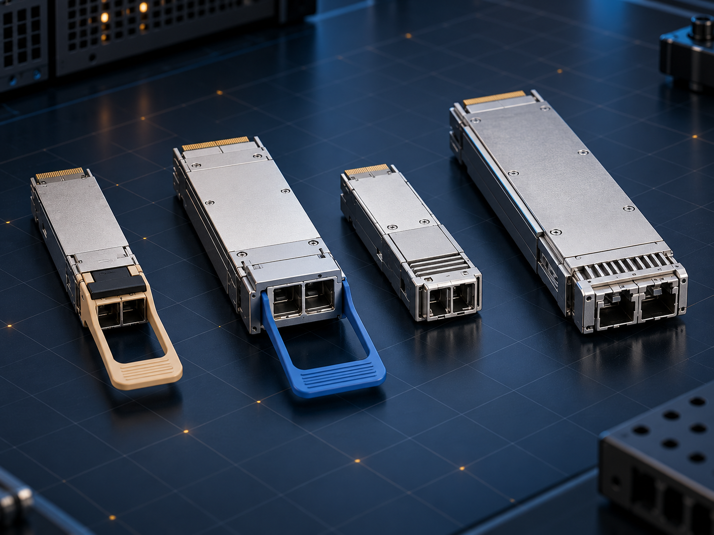
The 400G landscape
400G is not one transceiver design. It is an aggregate Ethernet rate, while the package, host electrical interface, optical-lane count, modulation, fiber and reach are defined by separate specifications. CFP8 was an early large format able to accommodate sixteen 25G NRZ or eight 50G PAM4 electrical lanes. QSFP-DD brought eight lanes into a footprint close to the QSFP family and became a major choice for dense switches. OSFP also uses eight lanes, but its larger body provides more thermal headroom and was designed with 800G and later generations in mind. CFP2-DCO remains relevant for coherent transport platforms where line performance and integrated digital-coherent functions matter more than maximum faceplate density.
Optical variants and reach
Inside data centers, 400GBASE-SR8 uses parallel multimode channels for short links. DR4 uses four 100G PAM4 optical lanes over single-mode fiber for roughly 500 meters and can support 4×100G breakout with the correct parallel-fiber infrastructure. FR4 and LR4 multiplex four wavelengths onto duplex single-mode fiber, with typical reaches of about 2 km and 10 km. OIF 400ZR uses dual-polarization 16QAM coherent modulation for unamplified single-wavelength links or amplified point-to-point DCI of up to about 120 km. Vendors also offer ZR+ variants, but reach, power and interoperability cannot be inferred from the name alone. Fixed 400G AOCs and DACs are alternatives: DAC offers low cost and power at very short reach, while AOC can simplify short fixed links where field-cleaned optical connectors are undesirable.
Practical qualification must treat the module, host and fiber plant as one system. Engineers should record lane configuration, modulation, FEC responsibility, connector loss, operating temperature and firmware before comparing alternatives. Testing should include cold start, repeated insertion, sustained traffic, diagnostic accuracy and fully populated thermal conditions. A specification identifies a permitted interface; it does not guarantee equal margin, software behavior or field support across every vendor combination.
A link budget should use worst-case transmit power and receiver sensitivity rather than typical values. Connector loss, splices, patch panels, wavelength-dependent loss, aging and a deliberate engineering reserve all belong in the calculation. Receive overload matters as well: an optic designed for a long span can receive too much power on a short patch unless attenuation is added. For parallel links, every lane must pass, and polarity must map each transmitter to the correct receiver. For wavelength-multiplexed links, both ends must use the same wavelength grid and lane order.
Operations planning is equally important. The monitoring system should collect temperature, voltage, transmit and receive power, alarms and pre-FEC error indicators where available. Baselines recorded after installation make gradual contamination, laser aging or rising temperature easier to distinguish from an abrupt fiber break. Cleaning procedures, inspection tools, spare placement and rollback instructions should be documented before production traffic depends on the link. A module that performs well in a bench test can still create long outages if field staff cannot identify the failing domain or replace it safely.
Power and cooling should be checked at the system boundary. Module wattage is only one part of consumption; host SerDes, retimers, fans and power conversion also contribute. Dense ports can be efficient per transported bit while creating local hot spots, so validation should use adjacent ports, realistic airflow and the highest supported inlet temperature.
Procurement should distinguish a standards-compliant sample from a host-qualified production part. Useful evidence includes a dated compatibility matrix, compliance report, reliability data, manufacturing change-control process and clear warranty ownership. Second sourcing only reduces risk when alternate modules pass the same electrical, optical, thermal and management tests. These checks prevent a familiar connector or matching headline rate from being mistaken for complete interoperability.
How to choose
Selection should start with the switch or router port, not with a module carrying a 400G label. The host must support the cage, per-lane rate, management interface, FEC and optical PMD. The fiber plant then determines multimode or single-mode, parallel fiber or duplex fiber, and the available loss budget after connectors, patch panels, splices and aging. QSFP-DD and OSFP can both carry 400G, but they are mechanically different and cannot be directly interchanged. Some OSFP systems can accept selected QSFP modules through an adapter, subject to explicit host support. Fully populated systems must also be checked for maximum module power, heatsink design, airflow and inlet temperature. A stable service requires both ends to match wavelength plan, lane mapping, FEC and protocol, not merely the aggregate speed.
Standards and verification
The QSFP-DD MSA hardware specification defines the cage, connector and high-speed electrical interface; the OSFP MSA defines OSFP mechanical, electrical and thermal requirements; IEEE 802.3 standards define multiple 400GBASE optical PMDs; and the OIF 400ZR implementation agreement defines an interoperable coherent interface. A project should cross-check the host compatibility matrix, module data sheet and intended software release, then test errors, FEC margin, startup, diagnostics and temperature on representative fiber. Standards compliance is necessary but does not replace host qualification. Sources include the QSFP-DD specification, OSFP MSA, Ethernet Alliance 400G material and the OIF 400ZR IA.